For the CMK2-CB-40-200-T0H3-D-Y/Z load sensing system, in the case of a fixed displacement pump system, the load pressure sensing oil circuit is led to the remote pressure regulating overflow valve. When the load is small, the set pressure of the overflow valve is also small; when the load is large, the set pressure is also large, but there is always a certain overflow loss. The variable displacement pump system introduces the load sensing oil circuit into the pump variable mechanism, causing the pump output pressure to rise with the increase in load pressure (always at a small fixed pressure difference), making the pump output flow equal to the actual system flow requirement, with no overflow loss, achieving energy saving. Installation notes: When installing, ensure that the arrow on the valve body is consistent with the direction of the medium flow. It should not be installed in places with direct dripping or splashing water. The solenoid valve should be installed vertically upwards; the solenoid valve has the same 90-degree rotation lifting action, the difference is that the spool body is spherical, with a circular through hole or channel through its axis. The ratio of the ball surface to the channel opening should be such that when the ball rotates 90 degrees, the ball surface should be fully presented at both the inlet and outlet, thereby cutting off the flow. DSM-12-270-P-A-B, DSBC-50-100-PPSA-N3 polyurethane air tube PUN-10X1,5-RT, DGC-K-40-900-PPV-A-GK, pressure regulating valve LR-ZP-A-D-1, pressure reducing valve LR-M2-N1/2-07GIKVAS-5-M5-NBR, AEVULQ-80-15-P-A, DGC-K-32-700-PPV-A-GK, plastic air tube PUN-E-6X0,8-SW-500 pressure reducing valve LR-M3-N3/8-16GI, pressure reducing valve LR-M2-G1/4-10GIGRLA-3/8-QS-10-RS-D, GRLA-1/8-BDSBC-32-40-D3-PPSA-N3, DSBC-125-320-PPVA-N3 installation flange YSRF-8-C, air tube PUN-4X0,75-S-1-BL pressure reducing valve LR-M2-G1/2-10I, pressure reducing valve LR-M1-N1/8-07GIAEVULQZ-25-20-P-A, AEVULQ-40-10-A-P-A, DSM-16-270-P-A-B, DSBC-63-50-PPVA-N3, polyurethane air tube PUN-16X2,5-BL, LFR-1/4-D-7-MINIM series pressure reducing valve LRB-M1-G1/4-07K, D series pressure reducing valve LR-3/8-D-7-I-MINIAEVULQZ-40-20-A-P-A, AEVULQ-20-25-P-A, double acting multi-face mounting?DMML-16-30-P-A, double acting anti-twist cylinder DZH-16-200-PPV-AD series lockable pressure reducing valve LRS-1/2-D-MAXI, LFR-1/2-S-BD series lockable pressure reducing valve LRS-3/8-D-7-MINI, D series pressure reducing valve LR-3/4-D-I-MIDI vacuum suction cup VAS-75-1/4-PUR,
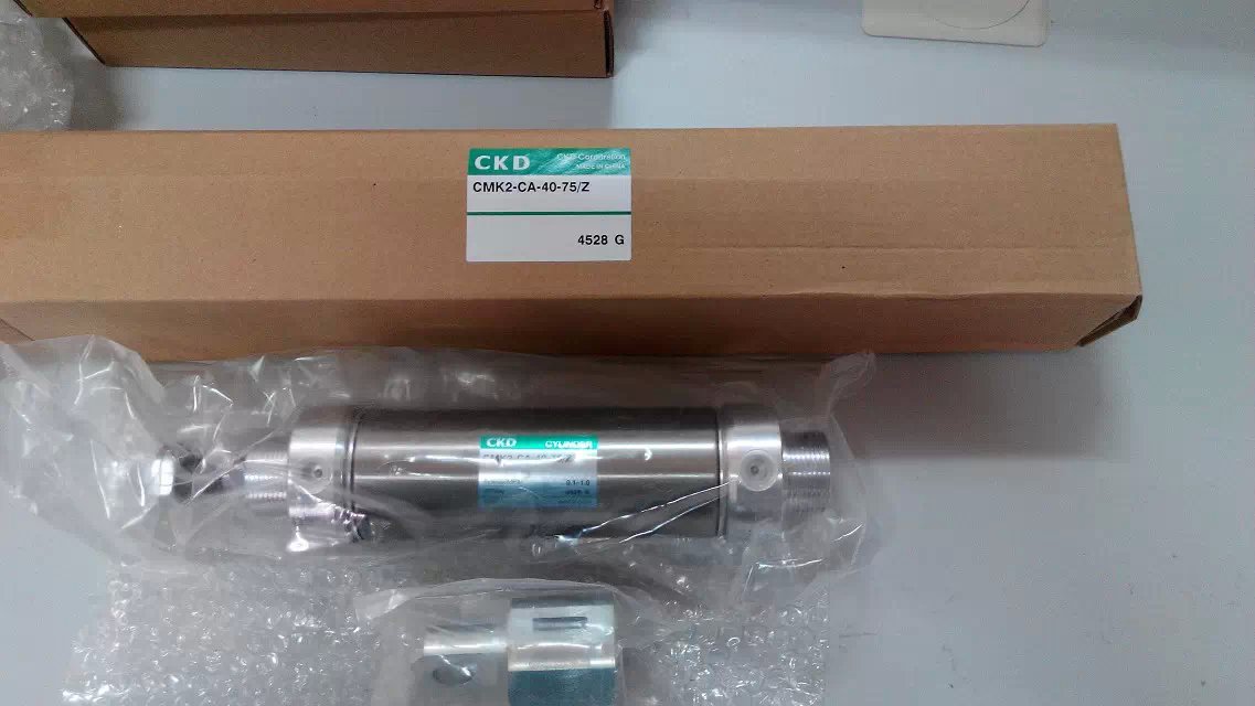
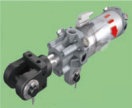
Double-acting cylinder CMK2-CB-40-200-T0H3-D-Y/Z belongs to the Air Pressure Cylinders series under CKD company, model number CMK2-CB-40-200-T0H3-D-Y/Z. To purchase or inquire about Double-acting cylinder CMK2-CB-40-200-T0H3-D-Y/Z, you can directly contact 158 0047 0089 (Mr. He).

 Double Acting Cylinder CMK2-CB-40-200-T0H3-D-Y/Z")