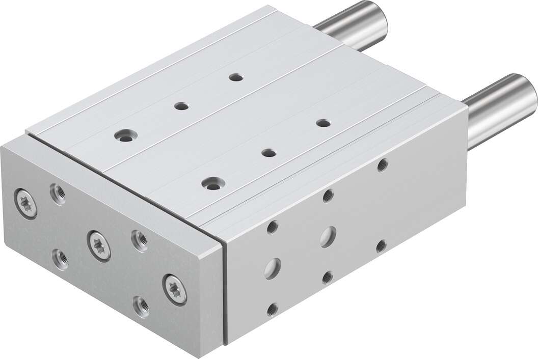
festoGuide cylinderDFM-100-160-P-A-KFReduced hose length minimizes flow requirements:—Short switch time—Short response time Optimal installation:—Shortens machine cycle—Increases quantity—Lower power consumption Manual control tools are convenient. The socket KMYZ-9 is suitable for valves of specifications CPE10 and CPE14, featuring integrated current reduction. Therefore, the continuous power supply rate for all CPE valves is 100%. Valve widths: 10 mm, 14 mm, 18 mm, and 24 mm, · Two-position three-way, two-position five-way, and three-position five-way valves, · Internal or external pilot air supply, · 24 V DC for all valve widths, · 110 or 220 V AC for valve widths of 18 and 24, · Hand-operated tools, with tool locking and unlocking, · Valves with a width of 10 mm come with an M5 interface insert, · All valve widths are equipped with two types of QS connectors, · Valve widths: 10 mm and 14 mm, · Two-position three-way, two-position five-way, and three-position five-way valves, · Internal or external pilot air supply, · 24 V DC, · Hand-operated tools, with tool locking and unlocking, · Circular plug, M8x1, 4-pin CPE18 basic valve, with ISO15218 standard interface pilot valve, with ISO 15218 standard interface, · Valve width: 18 mm, · Two-position three-way, two-position five-way, and three-position five-way valves, · Internal or external pilot air supply, · For 12, 24VDC and 24 V AC, without protective grounding, · For 110 and 220 V AC, with protective grounding, · Two-position three-way valves, · Hand-operated tools, no locking valve width module, used to fix valve width valve width module, used to fix valve width valve width module, used to fix valve width, · For valve widths: 10, 14, and 18 mm, · For two-position five-way and three-position five-way valves, · 2...10 valve positions, · For valve widths: 10, 14, and 18 mm, · For two-position three-way valves, · 2 ... 10 valve positions support components Support components, · For two-position five-way and three-position five-way valves · For two-position three-way valves blanking plugs Blanking plugs· For two-position five-way and three-position five-way valves · For two-position three-way valves air path module, with air supply Air path module, used for extension, · 2 valve positions, The ends of conduits 1, 3, and 5 can be open or closed, · When the air path board is fully loaded or using pressure zoning, the ends of the hoses are closed· 2 valve positions, · For two-position five-way and three-position five-way valves, · The ends of conduits 1, 3, and 5 can be open or closed air path module, with air supply End plate, used for additional air supply, · 3 valve positions, · For two-position five-way and three-position five-way valves, · The ends of conduits 1, 3, and 5 can be open or closed, · When the air path board is fully loaded or using pressure zoning, the ends of the hoses are closed· For if valves on the air path board
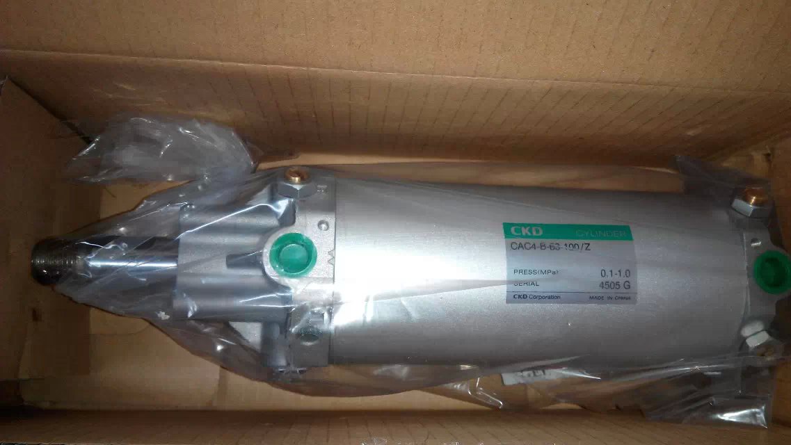
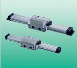
Guided Cylinder DFM-100-160-P-A-KF belongs to the Air Pressure Cylinders series under CKD company, model number DFM-100-160-P-A-KF. To purchase or inquire about Guided Cylinder DFM-100-160-P-A-KF, you can directly contact 158 0047 0089 (Mr. He).