The
festoGuide cylinderDFM-40-100-P-A-KF is designed for different medium temperatures; otherwise, the coil will burn out, the seals will age, and the lifespan will be severely affected. In hydraulic control valves used in pressure reducing valve engineering, the products are inspected and qualified by the manufacturer, with all markings complete and technical data meeting requirements. The arrow direction on the main valve body of the pressure reducing valve must be consistent with the flow direction of the pipeline system. In construction machinery, the electrical zero adjustment of the solenoid valve is always working in harsh environments, and its electrical zero point is susceptible to external environmental interference. Therefore, after replacing failed components, the electrical zero point should be checked, and recalibration should be performed for those that do not meet the requirements. The general detection method is as follows: supply power to the amplifier of the solenoid valve (usually 0-24V), ensure the valve core is in the de-energized state, and use a multimeter (DC range, 0.25V range) to detect the valve core displacement feedback signal. Under the condition that the valve core has not received an instruction, the valve core displacement feedback voltage should be zero. If it is not zero, the adjusting nut of the valve core displacement sensor should be adjusted until the valve core feedback voltage is zero. Intermittent exhaust is a normal phenomenon. If the pneumatic system is not working or is always exhausting, there are several possible situations: parameters and instructions for the pilot control valve; debugging period faults of the pilot control valve usually occur during the installation and debugging phase of the instrument. Once eliminated, they should not reappear under the same conditions in the future. Common debugging period faults are usually caused by improper installation, environmental interference, and the influence of fluid characteristics. Before installing a servo motor, the packaging must be opened on-site for an appearance inspection, including: whether the filter paper, sealant, and frame are damaged; whether the length, diagonal, and thickness dimensions meet the requirements; whether the frame has burrs and rust spots (metal frame); whether there is a product certificate, and whether the technical performance meets the design requirements. Then, check according to the method specified by the standard, and install immediately if qualified. 8. The service life of conventional products can reach over 1 million cycles. The design of the
festoGuide cylinderDFM-40-100-P-A-KF is a combination of experience and technology. Generally, sensors convert a physical quantity into another physical quantity that can be expressed intuitively through electrical circuits, such as converting into higher voltage and current signals that depend only on the measured physical quantity, and then displaying them. Therefore, several points need to be noted: the corrosion resistance of the buffer should also be considered. Since the buffer directly contacts the medium, it may be corroded or abraded by temperature, pressure, viscosity, or media containing solid particles and corrosive media. The corrosion or abrasion forms are diverse. The valve core and valve seat are particularly severely corroded or abraded due to the high-speed scouring of the medium. For media with low corrosion adjustment requirements, diaphragm valves can be used; for strongly corrosive and particulate media, ball valves and buffer-type valves can be adopted. The valve core and buffer valve seat must use special materials resistant to corrosion and wear, such as to meet the process conditions and usage requirements of synthetic ammonia and urea. Since the media are mostly liquid ammonia and ammonium carbamate, the working conditions of the valve core are extremely harsh. At this point, not only the control valve
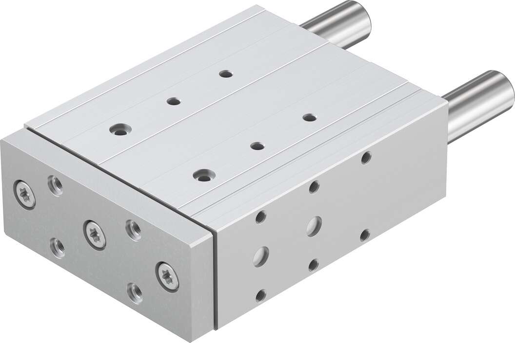
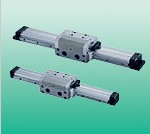
Guided Cylinder DFM-40-100-P-A-KF belongs to the Air Pressure Cylinders series under CKD company, model number DFM-40-100-P-A-KF. To purchase or inquire about Guided Cylinder DFM-40-100-P-A-KF, you can directly contact 158 0047 0089 (Mr. He).