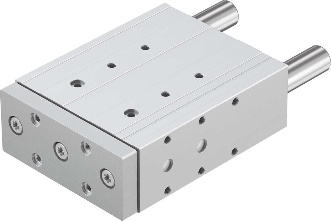
festo standard cylinder DFM-50-25-P-A-KF is generally suitable for clean media and should not be used for media containing solid particles and those with high viscosity. Diaphragm valves are suitable for working temperatures below 200°C and pressures below 1.0MPa for oil, water, acidic media, and media containing suspended solids, but are not suitable for organic solvents and strong oxidants. Depending on the purpose of use, function, and location, they can evolve into remote floating color sensor installations, etc. Installation considerations require a filter to be installed before the color sensor and should facilitate drainage requirements. Methods for inspecting hydraulic control valves. The booster works because of the difference in specific gravity between the core and the fiber filaments, causing the comet tail fibers to spread out and swing with the backwash water flow, generating a strong dragging force; the mutual collision of the filter media also intensifies the mechanical force exerted on the fibers in the water, and the irregular shape of the filter media causes the filter media to rotate under the action of the backwash water flow and air flow, strengthening the mechanical shear force exerted on the filter media during backwashing. The combined effect of these forces causes solid particles adhering to the surface of the fibers to easily fall off, thereby improving the cleaning efficiency of the filter media. Thus, the asymmetric fiber filter media also has the backwashing function of granular filter media. The automatic sewage filter uses a high-quality carbon steel cylinder, a stainless steel wedge-shaped filter screen with a special structure, a butterfly valve, and a sewage discharge device. Under normal working conditions, the valve plate is in the open position, the sewage outlet is closed, and all the water flows outward from the filter cylinder, with the waste being retained by the filter cylinder, concentrated in the rear section, to achieve normal water filtration. By instantaneously braking the workpiece carrier through the piston rod. 2. By activating the cylinder to release the workpiece carrier. 3. By spring force or air pressure, the piston rod extends again until the roller contacts the workpiece carrier. The workpiece carrier continues to move forward. 4. After the workpiece carrier passes, the piston rod extends to the terminal position. Stop the next tool carrier. Model, single-acting or double-acting, STA stop cylinder, STAF stop cylinder, with flange mounting parts, cylinder diameter ? [mm] stroke [mm] buffer, P with elastic buffer ring/pad at both ends position sensing, A through proximity switch typeR roller type, how to solve the rust problem of the pressure proportional valve; the selection of the flow characteristics of the pressure proportional valve can be done through theoretical calculation, but the methods and equations used are very complex. The flow characteristics of the pressure proportional valve refer to the relationship between the relative flow of the medium passing through the valve and the displacement (relative opening of the valve), and the ideal flow characteristics mainly include linear, equal percentage (logarithmic), parabolic, and quick opening types. The characteristic curve and valve core shape are shown in Figure 1 and Figure 2. The commonly used ideal flow characteristics are only linear, equal percentage (logarithmic), and quick opening types. The regulating valve parabolic flow characteristic is between linear and equal percentage, and can generally be replaced by the equal percentage characteristic, while the quick opening characteristic is mainly used for two-position regulation and program control. Therefore, the selection of the pressure proportional valve characteristics is actually the selection of linear and equal percentage flow characteristics.festo standard cylinder DFM-50-25-P-A-KF Common faults in the use of pilot control valves, some are due to the failure of the components of the instrument itself, others are
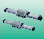
Guided Cylinder DFM-50-25-P-A-KF belongs to the Air Pressure Cylinders series under CKD company, model number DFM-50-25-P-A-KF. To purchase or inquire about Guided Cylinder DFM-50-25-P-A-KF, you can directly contact 158 0047 0089 (Mr. He).