The festo rodless cylinder DGC-K-25-600-PPV-A-GK is available with indirect pilot operation; for the lowest operating pressure difference that is close to or less than zero, direct acting or step direct operation must be selected. 3. The sliding parts of the filter barrel and piston rod must not be damaged to prevent the air filter from malfunctioning, damaging the piston rod seal and causing air leakage. The gripper is an automation basic component used to control the direction of fluids, belonging to the actuator; it is commonly used for mechanical control and industrial valves, controlling the direction of the medium to achieve control over the opening and closing of valves. The working principle is that the gripper has a sealed chamber with through holes opened at different positions, each hole leads to a different oil tube, the center of the chamber is a valve, and on both sides are two electromagnets, whichever side of the electromagnet coil is energized, the valve body will be attracted to that side, controlling the movement of the valve body to block or let out different oil outlet holes, while the oil inlet hole is always open, hydraulic oil will enter different oil outlet tubes, and then by the pressure of the oil to drive the oil filter piston, the piston drives the piston rod, the piston rod drives the mechanical equipment to move. Thus, by controlling the on/off of the electromagnet current, mechanical motion is controlled. 4. In engineering, the setting of hydraulic control valves should have sufficient space for management, operation, installation, and maintenance, and should meet the requirements of the pipeline for the valve. 2. The function of the joint relief valve is: pressure regulation, overflow, overload protection. The pressure reducing valve is to reduce pressure, reducing the pressure in a certain part of the hydraulic system. They have different uses and therefore cannot be substituted for each other. It mainly consists of stator 1, rotor 3, oil distribution shaft 2, bushing (not shown in the diagram), and plunger 4. Several radial holes are evenly distributed on the rotor 3, and the plunger 4 can slide freely in these holes. The oil distribution shaft 2 divides the inner hole of the bushing into two oil distribution chambers, which are connected to the suction and pressure oil ports of the pump through the axial holes on the oil distribution shaft 2. The stator 1 and the rotor 3 are eccentrically installed. When the rotor 3 rotates counterclockwise as shown, the plunger 4 gradually extends outward during the lower half of the cycle, the volume of the plunger hole increases to form a partial vacuum, and the oil in the oil tank enters the plunger hole through the oil inlet on the oil distribution shaft 2 and the oil chamber, which is the suction process. When the plunger 4 moves to the upper half of the cycle, the stator 1 presses the plunger 4 into the plunger hole, the sealed volume of the plunger hole becomes smaller, and the oil in the hole is pressed into the system through the oil chamber and the oil outlet, which is the pressure oil process. Each rotation of the rotor 3 causes each plunger to perform suction and pressure oil once. The output flow is determined by the eccentricity between the stator 1 and the rotor 3. If the eccentricity is adjustable, it becomes a variable displacement pump, as shown here is a variable displacement pump. If the direction of the eccentricity changes, the suction and pressure oil ports also change positions, then it becomes a bidirectional variable displacement pump. (2) Tool preparation: various wrenches, hand tools, chisels, files, pry bars, 24-36 volt work lights, various grinding tools, screwdrivers, grinding bottom plates, full pipes, sledgehammers, tool aids, scissors, packing tool for changing packing, hand chain for repairing large valves, etc. How does the proportional valve work; proportional pressure reducing valve VPPE – 5, 2 proportional pressure reducing valve with display VPPE...E1 – 8, 3 setting point module MPZ for generating 6+1 analog voltage signals 11, 4 digital quantity
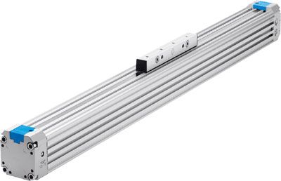
Rodless cylinder DGC-K-25-600-PPV-A-GK belongs to the Air Pressure Cylinders series under CKD company, model number DGC-K-25-600-PPV-A-GK. To purchase or inquire about Rodless cylinder DGC-K-25-600-PPV-A-GK, you can directly contact 158 0047 0089 (Mr. He).