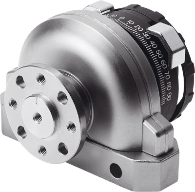
The festo rotary cylinder DSM-10-180-P-A spring's working pressure level refers to the range of operating pressures allowed for a particular spring. Within this pressure range, the set pressure of the safety valve (i.e., the adjusted pressure) can be adjusted by changing the pre-tensioned compression of the spring. Safety valves with the same nominal pressure can be divided into various different working pressure levels based on the design requirements of the spring. The specific classification is based on the premise that the upper and lower limits of each working pressure level can meet the action performance indicators specified by relevant standards. When selecting a safety valve, the working pressure level of the valve should be determined based on the required set pressure value. Two-way three-port valves are normally open or normally closed depending on the chosen connection method. G-threaded connections are selected based on need, and rotary lever valves are mechanically driven by a camshaft. The control range can be selected by adjusting the position of two components of the control drive. Drive method: Direct-acting round head valve, Rotary lever valve. Operating medium: Filtered compressed air, lubricated or unlubricated, vacuum. 1) Structural features: Lift valve, direct-acting. Installation method: Two through holes installed, two-way three-port valve normally closed, normally open, converted by changing the top position of the valve body. Two-way four-port valve with pilot control, small driving force. Blocking the exhaust port can be used as a two-way two-port valve, when the working pressure is 6 bar, the relationship between the driving force F and the driving stroke and driving distance L. Spring feeler valve, this type of valve uses pilot control and requires only a small driving force, making it particularly suitable for controlling objects in different positions or not on the same plane. The valve can be driven in any direction perpendicular to the axis of the spring feeler. The drive conversion device is installed on the left (the number 1 on the conversion device is above the number 1 on the housing), the drive conversion device is installed on the right (the number 1 on the conversion device is above the number 2 on the housing), initial position 2, drive position 3, drive direction, 4 minimum distance between cams, 5 lowest position of control rail or cam, 6 empty return, 7 minimum switching distance. 2. For lubricated cylinders, an oil mist lubricator with appropriate flow rate should be installed; for non-lubricated cylinders, due to the pre-added lubricating grease inside the cylinder, they can be used for a long time. The cylinder opening and closing operation end should be square tenon, and the size is standardized, and it should face the ground so that people can operate directly from the ground. Valves with belts are not suitable for underground pipelines. Display disk for cylinder opening and closing degree; the scale line for cylinder opening and closing degree should be cast on the gearbox cover or on the housing of the display disk after the direction is changed,一律 facing the ground, the scale line should be painted with fluorescent paint to make it stand out;吸入electromagnetic valve air中的hard particle dust and incomplete combustion产生的carbon deposits, unfiltered metal particles in the lubricating oil, etc. abrasive. Enter the cylinder wall and piston, piston ring mating surface between, with the piston in the cylinder reciprocating movement, causing abrasive wear of the cylinder. Without connecting plate, interface specifications on the shell M5 or M7 will filter, pressure reducing valve and oil mist lubricator into one unit. Large flow, high efficiency removal of impurities, good regulation characteristics, small hysteresis. By locking the rotating handle to prevent the setting, parameter values are tampered with can be locked.
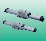
Rotary Oscillating Cylinder DSM-10-180-P-A belongs to the Air Pressure Cylinders series under CKD company, model number DSM-10-180-P-A. To purchase or inquire about Rotary Oscillating Cylinder DSM-10-180-P-A, you can directly contact 158 0047 0089 (Mr. He).