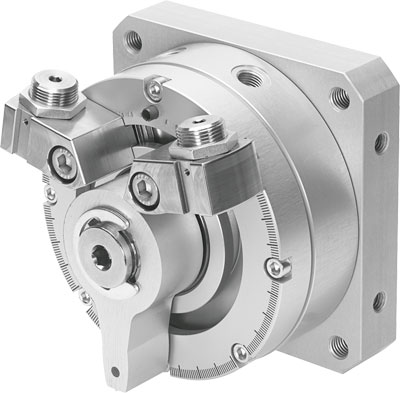
The festo rotary cylinder DSM-8-90-P-A oil chamber is connected to the pump's suction and pressure oil ports through the axial holes on the oil distribution shaft 2. The stator 1 and rotor 3 are eccentrically installed. When the rotor 3 rotates counterclockwise as shown in the diagram, the plunger 4 gradually extends outward during the lower half of the cycle, increasing the volume of the plunger hole to form a local vacuum. The oil in the oil tank enters the plunger hole through the suction port and oil chamber on the oil distribution shaft 2, which is the suction process. When the plunger 4 moves to the upper half of the cycle, the stator 1 presses the plunger 4 into the plunger hole, reducing the sealed volume of the hole. The oil inside the hole is then pressed into the system through the oil chamber and discharge port, which is the pressure oil process. Each plunger吸油 and 压油 once per rotor revolution. The output flow is determined by the eccentricity between the stator 1 and rotor 3. If the eccentricity is adjustable, it becomes a variable displacement pump, as shown here. If the direction of the eccentricity changes, the suction and discharge ports also switch positions, becoming a bidirectional variable displacement pump. To reduce the operating torque of the solenoid valve and increase the reliability of the seal, oil-sealed ball valves have been developed in recent years, which inject special lubricating oil between the sealing surfaces to form an oil film. This enhances the sealing and reduces the operating torque, making them more suitable for high-pressure and large-diameter ball valves. (1) Fast action, low power, and compact design. The response time of solenoid valves can be as short as a few milliseconds, and even pilot-operated solenoid valves can be controlled within tens of milliseconds. Due to their self-contained circuit, they are more responsive than other self-controlled valves. A well-designed solenoid valve coil consumes very little power and is an energy-saving product; it can also be designed to automatically maintain the valve position, consuming no power at all when not in use. Solenoid valves are small in size, saving space and also lightweight and aesthetically pleasing. When automatic control valves are working, some auxiliary valves and fittings must be used on the pipeline. For example, the isolation bypass shown in Figure 1 is a typical installation method, requiring three manual valves, where manual valve 1 is the bypass valve, manual standby. Manual valves 2 and 3 are isolation valves, ensuring the online maintenance of automatic control valve 5. Of course, two three-way connectors 4 and two coupling fittings 6 are also needed. This pipeline system takes up a lot of space, is time-consuming to install, and prone to leakage. The ZDF series multi-function solenoid valve cleverly eliminates these additional accessories while still having the function of an isolation bypass, thus winning the Geneva International New Technology Gold Medal. Automatic control valves require a filter to be installed in front. The use of multiple automatic control valves together often requires the installation of a check valve to prevent interference between pipelines. Single solenoid valves, combined solenoid valves, and solenoid valves with filters have all played a role in simplifying the pipeline. (Our company has also launched a back-flushing filter valve, which combines the functions of switching and filtering, and can flush the filter element without removing the valve, earning Sino-US invention patents.) Introduction to the use and incorrect installation of the cylinder repair kit; the cylinder (10) and two guide shafts (16) are fixedly installed on the left and right side plates (17) connected to the base plate (12), the cylinder (10) drives the workbench (13) connected to the slider (1) to perform horizontal movement, the horizontal movement of the rodless cylinder is achieved by the photoelectric switch (2), solenoid valve, and control circuit. The positioning column (4) connected to the positioning cylinder (3) is controlled by the two-position three-way valve and the rodless cylinder return control pneumatic two-position five-way valve to extend and retract.
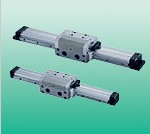
Rotary Oscillating Cylinder DSM-8-90-P-A belongs to the Air Pressure Cylinders series under CKD company, model number DSM-8-90-P-A. To purchase or inquire about Rotary Oscillating Cylinder DSM-8-90-P-A, you can directly contact 158 0047 0089 (Mr. He).