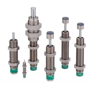
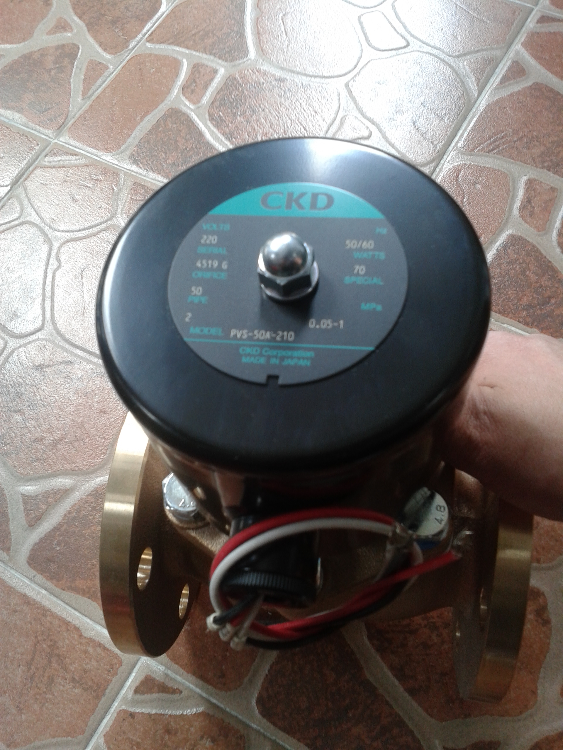
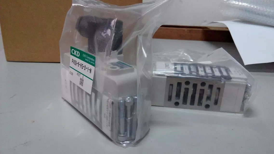
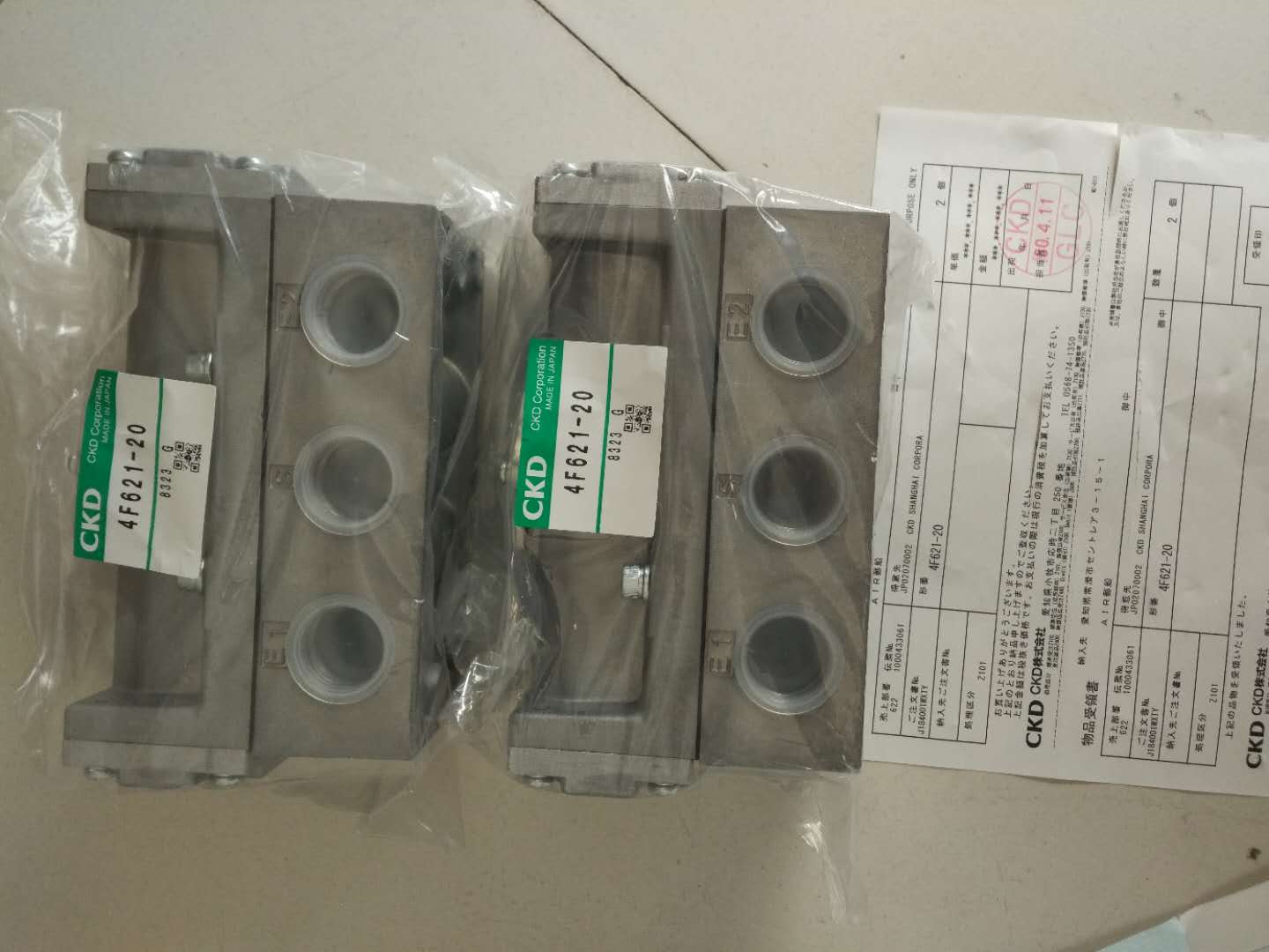
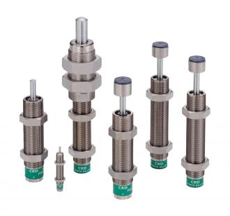
CKD buffer FCK-L-0.3-C self-adjusting buffer assembly position Any position detection No large impact speed 3 m/s short reset time 0.3 s long reset time 1 s work mode Single acting push action corrosion resistance grade CRC2 – medium corrosion effect ambient temperature -10 ... 80 °C buffer length 20 mm maximum braking force 2,000 N maximum energy consumption per stroke 30 J maximum energy consumption per hour 64,000 J maximum residual energy 0.16 J reset force 6 N product weight 185 g installation type with locking nut material notes Contains no brass and PTFE complies with RoHS material information, seal NBR material information, housing steel electroplated material information, piston rod high alloy steel adjustable or self-adjusting · straight or progressive characteristics · buffer and end position sensing combination · complies with ATEX directive for specific types, suitable for potentially explosive working environments hydraulic buffer with pressure control throttling function · adjustable buffer hardness · hydraulic oil can be refilled (exception mechanical buffer with adjustable rubber buffer · adjustable buffer hardness · elastic rubber buffer to achieve specified metal end position · complete external mounting thread, plus internal hexagon · small slide type cylinder self-adjusting hydraulic buffer with displacement control throttling function · quickly increase buffer force curve · short buffer stroke · suitable for rotary cylinders · maintenance-free · complete external mounting thread · swing cylinder DSM · straight cylinder DGPL · straight cylinder DGC · swing/straight unit DSL · straight unit SLE hydraulic buffer with displacement control throttling function · quickly increase buffer force curve · short buffer stroke Suitable for rotary cylinders · maintenance-free · complete external mounting thread, plus internal hexagon · swing cylinder DSM-B · swing/straight unit DSL-B hydraulic buffer with displacement control throttling function · progressive pressurization buffer force curve · long buffer stroke Suitable for low vibration work · short cycle time · maintenance-free · complete external mounting thread, plus wrench engagement surface · straight cylinder DGC · straight module HMP, HMPL gripper module HSP, DYSW · hydraulic buffer with displacement control throttling function · progressive pressurization buffer force curve · long buffer stroke Suitable for low vibration work · short cycle time maintenance-free · complete external mounting thread, plus internal hexagon · small slide type cylinder DGSL buffer element self-adjusting self-adjusting progressive hydraulic buffer (YSRW) · progressive pressurization buffer force curve · adjustable buffer stroke end position sensing, precise end position adjustment through proximity switch · buffer element YSRWJ can be used in various applications in gripping and assembly technology.CKD buffer,/
Buffer FCK-L-0.3-C belongs to the Speed regulating valve, check valve, auxiliary components series under CKD company, model number FCK-L-0.3-C. To purchase or inquire about Buffer FCK-L-0.3-C, you can directly contact 158 0047 0089 (Mr. He).
1. Cylinders: Used to convert the energy of compressed air into mechanical energy to produce linear motion.
2. Pneumatic valves: Used to control the direction, speed, and pressure of airflow, regulating the operation of pneumatic systems.
3. Pneumatic motors: Devices that convert compressed air into rotary motion.
4. Air tubes and connectors: Used to connect various components in pneumatic systems and transmit air.
Yes, CKD pneumatic components require regular maintenance to ensure normal operation and extend service life. Key maintenance points include:
- Regularly check and replace seals and gaskets to prevent air leakage.
- Inspect and clean filters to ensure clean air quality.
- Lubricate moving parts to reduce wear and improve efficiency.
- Check air tubes and connectors to ensure secure and undamaged connections.
When selecting the appropriate CKD pneumatic components, consider the following factors:
Application requirements: Understand the specific working environment and tasks, such as load, speed, and stroke.
Air source conditions: Ensure that the pressure and flow of the air source meet the component’s requirements.
Installation space: Confirm available space and choose components of suitable size.
Environmental factors: Consider the temperature, humidity, and potential corrosiveness of the working environment to select suitable materials and designs.
Common pneumatic system faults include:
Air leakage: Causes efficiency decline; check seals, connections, and tubes, find leak points, and repair or replace.
Stuck cylinder piston: Possibly caused by dirt or insufficient lubrication; clean the piston and add lubricant.
Valve failure: Check electrical control signals, ensure smooth airflow, and verify if the valve itself is damaged.
Insufficient pressure: Inspect air source pressure, filters, and piping to ensure no blockage or leakage.