SCA2-Q2-CB-100R-300-R-T0H3-T-Y through proximity switch air source – only right or both ends, DL only left or both ends slider, GP protected type circulating ball bearing guide lubrication – standard, H1 lubrication certification for food, lubrication function – standard, C lubrication connection piece additional slider, KL additional slider, left, KR additional slider, right, clamping device – none 1H single channel drive mode – none, PN pneumatic EU certification, groove cover L for sensor groove terminal position mechanical limit, YWZ1 variable terminal position, one end, YWZ2 variable terminal position, both ends, intermediate position Z1 1 intermediate position Z2 2 intermediate positions Z3 3 intermediate positions, working and environmental conditions cylinder diameter working pressure [bar] working medium compressed air in accordance with, working/leading medium notes lubricatable work, ambient temperature 1) [°C] –10 … +60, food safety 2) see supplementary material information, corrosion resistance grade CRC3) 1, 1) note proximity switch operating range, 2) see, 3) corrosion resistance grade 1, in accordance with FN 940 070 standard, low corrosion resistance. Transport and storage protection. Also applicable to invisible internal areas or components located under the cover (e.g., cylinder pin). Explosion-proof temperature grade –10°C ≤ Ta ≤ +60°C, CE marking (see declaration of conformity) in accordance with EU explosion-proof directive (ATEX), EX2 certification ATEX explosion-proof category, for gas II 3G, explosion-proof type, for gas c T4 X, ATEX explosion-proof category, for dust II 3D, explosion-proof type, for dust c T120°C X, EX3 certification ATEX explosion-proof category, for gas II 2G, explosion-proof type, for gas c T4 X, example: cylinder DGC-25-1500 horizontal position withstands a force of 300 N. Total length of the cylinder is: l = working stroke + L1 (see dimensions) = 1500 mm + 200 mm = 1700 mm, according to the chart, the support interval for the cylinder DGC-25 to withstand a force of 300 N is 1300 mm. In this example, profile mounting parts are required because the large support interval (1300 mm) is less than the total length of the cylinder (1700 mm). 6312D-331-PP-501JM M0D:GL02, 57D-14-611BA52A-11-D0A-DM-DDAJ-1JD, 34C-ABA-GDFA-1BA411A-D0D-DM-DDAA-1BA, 161B-611JM M0D:M681431A-D0D-DM-DDAA-1BA, 411A-D0A-DM-DDAJ-1JM413A-00D-DM-DDAA-1BA, 36A-SCC-JDA0-1KA433A-00D-DM-DDAA-1BA, 57D-16-121BA27A-
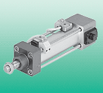
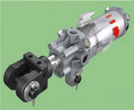
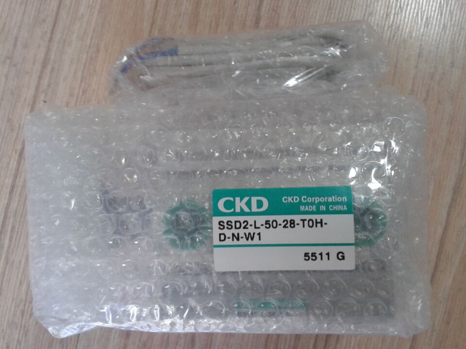
Medium-sized cylinder SCA2-Q2-CB-100R-300-R-T0H3-T-Y belongs to the Air Pressure Cylinders series under CKD company, model number SCA2-Q2-CB-100R-300-R-T0H3-T-Y. To purchase or inquire about Medium-sized cylinder SCA2-Q2-CB-100R-300-R-T0H3-T-Y, you can directly contact 158 0047 0089 (Mr. He).