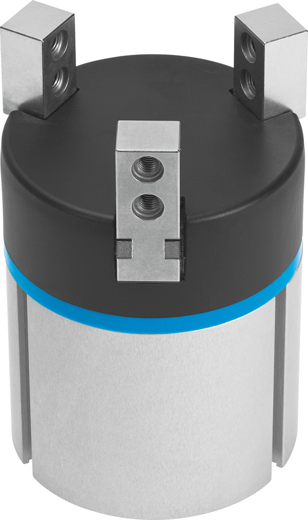
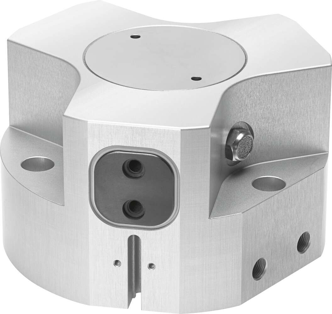
The festo pneumatic gripper HGPT-35-A-B housing is made of die-cast zinc, material information, bowl PC air source treatment device FRC, with connecting plate, interface specification Gx, QS4 or QS6 air source treatment device FRC, without connecting plate, interface specification on the housing M5 or M7 combines the filter, pressure reducing valve, and oil mist eliminator into a single unit. High flow rate, efficient removal of contaminants, good regulation characteristics, small hysteresis. Locking the rotating handle prevents the setting parameters from being tampered with. Two pressure adjustment ranges are available: 0.5 ... 7 bar and 0.5 ... 12 bar. Two pressure gauge interfaces for different installation options with manual, semi-automatic, or fully automatic condensate drainage are optional. Filter: three-piece detection principle structure, safety light curtain with multiple infrared emitters spaced evenly on one side and infrared receivers on the other. Each infrared emitter corresponds to several infrared receivers. When the emitter sends out a light signal, it can reach the infrared receiver smoothly. When the infrared receiver does not receive the modulated signal smoothly, it cannot perform photoelectric conversion. In this way, by analyzing the internal circuit state, the presence or absence of an object can be detected. The corrosion resistance of the buffer should also be considered. Since the buffer is in direct contact with the medium, it may be corroded or eroded by temperature, pressure, viscosity, or media containing solid particles and corrosive media. The corrosion or erosion patterns are diverse, and the valve core and valve seat are particularly severely corroded or eroded by the high-speed scouring of the medium. For corrosive media with low regulation requirements, diaphragm valves can be used; for strongly corrosive and particulate media, ball valves and buffer-type valves can be used, and the valve core and buffer valve seat should be made of special corrosion-resistant and wear-resistant materials. For example, to meet the process conditions and usage requirements of synthetic ammonia and urea, the medium is mostly liquid ammonia and ammonium carbamate, etc., and the working conditions of the valve core are extremely harsh. At this point, not only are there certain material requirements for the regulating valve, but there are also some special structural requirements to prevent the failure of the regulating valve. Therefore, when considering the manufacturing materials of the regulating valve, the suitability of the valve structure form should also be considered. Only in this way can better measurement results be achieved. The cylinder operation process When the valve is at the center opening, due to the water flow torque, the operating mechanism requires self-locking. The relationship between the opening of the cylinder operation process and the flow rate is basically a linear fractional change. If used to control the flow rate, its flow characteristics are also closely related to the pipe flow resistance. For example, if two pipelines are installed with the same valve diameter and method, but the pipe loss coefficients are different, the valve flow will also be greatly different. Groove gate valve cylinder operation process related to emergency repair work solutions: Remove the cylinder pull spring, then remove the jack, remove the connecting pin of the lever arm and the guide sleeve and the rear support, remove the lever arm, so that the guide sleeve is completely exposed. In the closed state, there is a huge steam pressure difference before and after the valve, the valve butterfly is tightly pressed against the bottom, and the stem will not easily move. At this point, rotate the guide sleeve clockwise until the pin hole is aligned, reinstall the pin and weld the sealing point firmly, restore it.
Pneumatic gripper HGPT-35-A-B belongs to the Clamping Jaws, Clamping Plates series under CKD company, model number HGPT-35-A-B. To purchase or inquire about Pneumatic gripper HGPT-35-A-B, you can directly contact 158 0047 0089 (Mr. He).