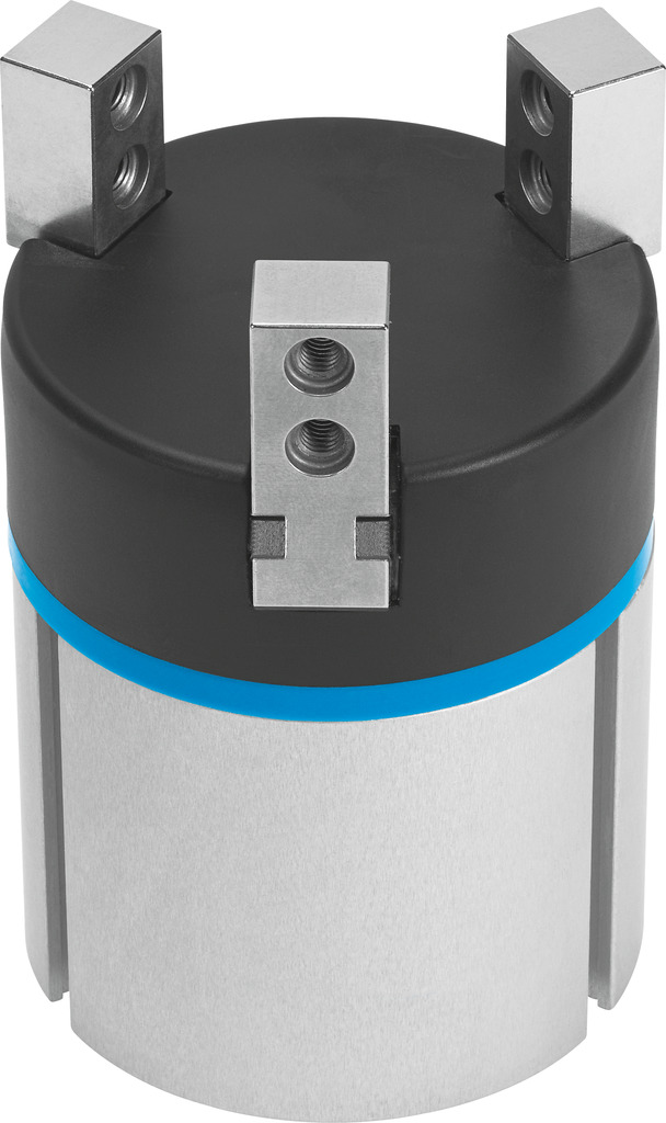
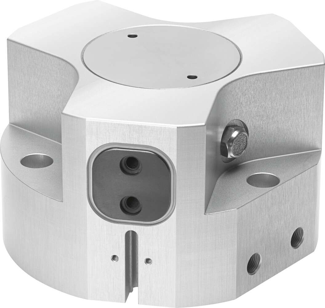
The festo pneumatic gripper HGPT-40-A-B actuator requires multi-point positioning control, and precise control or synchronous tracking of the actuator's operating speed and torque is necessary. These controls cannot be achieved with traditional pneumatic control, but electric actuators can easily achieve such control. Thus, rotary clamping cylinders are more suitable for simple motion control, while electric actuators are often used for precise motion control applications. When the rotary clamping cylinder has a large-area leak at the joint surface with a gap of about 0.50mm, to reduce the amount of scraping work, the coating process can be used. Use the cylinder as the anode and the coating tool as the cathode, repeatedly brush the electrolyte solution on the joint surface of the cylinder. The thickness of the coating should be determined according to the size of the gap on the cylinder joint surface, and the type of coating should be determined according to the material of the cylinder and the repair scraping process. Spraying is a method of forming a coating with the required properties by heating metal powder to melting or plastic state with a special high-temperature flame spray gun and then spraying it onto the treated cylinder surface. The characteristics are simple equipment, convenient operation, and a solid coating. The temperature of the cylinder after spraying is only 70℃—80℃, which will not cause deformation of the cylinder, and a heat-resistant, wear-resistant, and corrosion-resistant coating can be obtained. Note that before electroplating and spraying, the cylinder surface must be ground, degreased, and roughened, and after electroplating and spraying, the coating must be scraped to ensure the tightness of the joint surface. The brake must indeed be able to maintain, and necessary mechanical locking mechanisms must be set up to achieve the necessary balance state. Notes on valve islands: There are two types of valve islands, normally closed and normally open. The normally closed type is in a closed state when the power is off, and when the coil is energized, electromagnetic force is generated, causing the moving iron core to overcome the spring force and directly open the valve, allowing the medium to pass through; when the coil is de-energized, the electromagnetic force disappears, and the moving iron core returns to its original position under the action of the spring force, directly closing the valve port, and the medium does not pass. The structure is simple, the action is reliable, and it works normally under zero pressure difference and micro vacuum. The normally open type is exactly the opposite. It adopts a combination of primary and secondary valve opening, with the main valve and the pilot valve opening step by step under the direct action of electromagnetic force and pressure difference. When the coil is energized, electromagnetic force is generated causing the moving iron core and the stationary iron core to attract each other, and the pilot valve port opens. Since the pilot valve port is located on the main valve port, and the moving iron core is connected with the main valve core, at this time the pressure in the upper chamber of the main valve is relieved through the pilot valve port, and under the combined action of pressure difference and electromagnetic force, the main valve core moves upward, opening the main valve and allowing the medium to flow. When the coil is de-energized, the electromagnetic force disappears, at this time the moving iron core closes the pilot valve port under the action of its own weight and spring force, at this time the medium enters the upper chamber of the main valve core through the balance hole, causing the pressure in the upper chamber to rise, at this time under the action of spring return and pressure, the main valve closes, and the medium is cut off. The structure is reasonable, the action is reliable, and it also works reliably at zero pressure difference. The working process of the rodless cylinder is: the drive shaft 1 drives the cylinder body 2 to rotate, the cylinder body 2 has an odd number of piston holes distributed evenly, piston holes 6 are equipped with pistons 5, the head of the piston 5 presses tightly against the inclined plate 3 through the slider 4. The structure of the servo motor 闸阀 is divided into electromagnetic valves according to the valve rod structure and the movement mode, the valve rod drives the gate plate to rise and fall together, the transmission thread on the valve rod is outside the valve body, therefore, the opening and closing and position of the gate plate can be visually determined according to the movement direction and position of the valve rod, and the transmission thread is convenient for lubrication and not subject to fluid corrosion
Pneumatic gripper HGPT-40-A-B belongs to the Clamping Jaws, Clamping Plates series under CKD company, model number HGPT-40-A-B. To purchase or inquire about Pneumatic gripper HGPT-40-A-B, you can directly contact 158 0047 0089 (Mr. He).