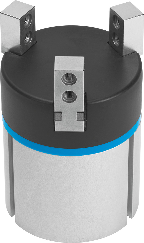
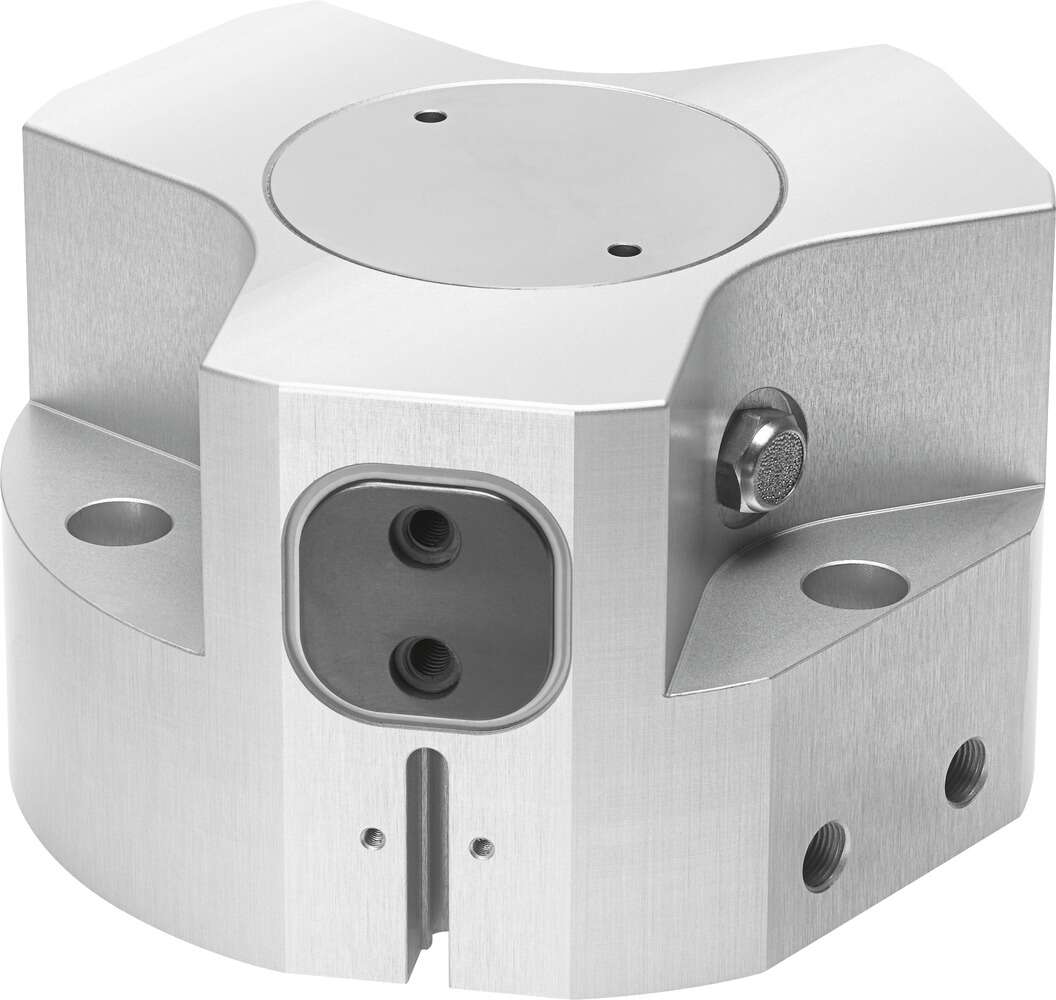
The festo pneumatic gripper DHWS-40-A-NC drives the valve core movement, thereby changing the valve's conductive state; the so-called dry or wet only refers to the coil's working environment, which makes little difference to the valve action. However, we know that the inductance of a hollow coil is different from the inductance after adding an iron core to the coil, the former being smaller and the latter larger. When the coil is energized with AC, the impedance generated by the coil also varies, for the same coil, with the same frequency of AC, the inductance will change with the position of the iron core, that is, the impedance changes with the position of the iron core, when the impedance is small, the current flowing through the coil will increase; when the solenoid valve coil is energized (on), the iron core is attracted, forming a closed magnetic circuit, that is, the inductance is designed to be at its maximum state, its heating is normal, but if the iron core cannot be smoothly attracted when energized, the coil inductance decreases, the impedance decreases, and the current increases accordingly, which leads to excessive coil current, affecting the life. Therefore, oil pollution causes the iron core movement to be hindered, the action is slow when energized, and even cannot be normally fully attracted, causing the coil to be frequently in a state of impedance less than normal when energized, which may be the reason for the coil's frequent overheating. The valve island with multi-sided installation of cylinders has made a grand debut; the valve island can only be used for drivers with sensor rails up to specification 35: there are two types of cylinder barrel shapes that can only use T-slot sensors CRSMT-8M and SMT-8M-A, which can only be used for the profiles shown in the figure below, such as: DSBF for example: CDC proximity switch SMT/SME-8, used for T-slot peripheral components list, installation components and accessories proximity switch 1 SMT-8M-A-…, with cable 7, 2 SME-8M-…-OE, with cable 15, 3 SME-8-FM-…-K-…, with cable 45, CRSMT-8-K-…, with cable, corrosion resistant 27, 4 CRSMT-8M-…, with cable 23, 5 SMT-8G-…-OE, with cable 39, 6 SME-8M-…-M…, with cable and plug 15, 7SMT-8-SL-…, with plug 27, SME-8-SL-…, with plug 31, 8 SME-8-S-…, with cable and plug 31, 9 SMT-8G-…-M…, with cable and plug 39, aJ SMTO/SMTSO, with plug 54, SMEO-8E, with cable or plug 59, aA SDBT-BSW, anti-weld field 48, connecting cable, aB NEBU-M…G… 67, aC NEBU-M…W… 67, installation components and accessories, aD installation component SMBR-8-8/100-S6, high temperature resistant 63, aE installation component SMBR 63, aF installation component CRSMB, corrosion resistant 64, aG installation component SMB-8-FENG 64, aH installation part SMBZ-8-… 66, aI sensor bracket DASP-M4-… 65, bJ installation
Pneumatic gripper DHWS-40-A-NC belongs to the Clamping Jaws, Clamping Plates series under CKD company, model number DHWS-40-A-NC. To purchase or inquire about Pneumatic gripper DHWS-40-A-NC, you can directly contact 158 0047 0089 (Mr. He).